Excitement About Wedge Barriers
Wiki Article
Wedge Barriers for Beginners
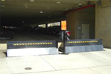
14 and the surface area 12 to which the obstacle 10 is protected may be made from concrete - Wedge Barriers. 2, the barrier 10 is installed to or consists of a support or subframe (e. g., support 30 displayed in FIG. 2 )protected under the surface area 12. The bather 10 may be bolted to the anchor or protected to the support by other mechanical bolts. In the illustrated embodiment, the obstacle 10 includes a wedge plate 16, which includes a section that is significantly parallel with the surface area 12 when the barrier 10 is in the retracted placement. Simply put, automobiles or people might overlook the barrier 10 when the obstacle 10 remains in the pulled back position and experience slight elevation about the surface 12 while on the obstacle 10. As talked about carefully below, when the obstacle 10 remains in the released setting, the wedge plate 16 is held and sustained in an elevated placement by a training mechanism of the barrier 10. In addition, the elements 18 might be bolted or otherwise mechanically paired to each other. In this fashion, repair work or replacement of several parts 18 might be streamlined and structured. That is, repair work or substitute of single parts 18 might be done quicker, quickly, and cost efficiently. FIG. In particular embodiments, the support 30 might be a steel frame consisting of plates, beams(e. g., I-beams ), and/or other frameworks that are secured within the foundation 14, which might be concrete. At the surface 12, an upper side 28 of the support 30 might be at least partly exposed , thus allowing the attachment of the barrier 10 to the anchor 30. g., threaded holes)in several light beams or plates of the anchor 30 might be exposed to the surface 12. In this way, additional hints screws 32 or other mechanical fasteners might be made use of to secure the barrier 10 to the support 30. As the obstacle 10 is mounted to the surface area 12 of the structure 14, collection of debris and various other product beneath the barrier may be reduced, and elements of the bather 10 may not be exposed to below quality settings. As indicated by referral character 52, the training device 50 consists of components disposed below the wedge plate 16. For instance, the parts 52 under the wedge plate 16 might consist of an electromechanical actuator, a cam, one or even more camera surface areas, etc. Furthermore, the training mechanism 50 includes a springtime setting up 54
The springtime rod 58 is combined to a camera(e. g., camera 80 revealed site web in FIG. 4) of the training system 50. The springs 60 disposed concerning the springtime pole 58 are held in compression by spring supports 62, including a repaired spring assistance 64. That is, the set springtime support 64 is dealt with about the structure 14 and the remainder of the bather 10.
Wedge Barriers Fundamentals Explained
g., spring assistance 65 )may be taken care of to the end of the spring pole 58 to allow compression of the springtimes 60. As the springs 60 are compressed in between the spring sustains 62, the spring assembly 54 creates a pressure acting on the web cam coupled to the springtime pole 58 in a direction 66. The staying pressure applied to the cam webcam deploy release wedge plate 16 may might provided by an electromechanical actuator 84 or other actuator. The springtime assembly 54 and the actuator 84(e. g., electromechanical actuator)might run with each other to translate the webcam and lift the wedge plate 16.
As mentioned over, in the released position, the wedge plate 16 serves to block accessibility or traveling past the barrier 10. The barrier 10(e. g., the wedge plate 16 )might block pedestrians or automobiles from accessing find this a building or path. If a vehicle is taking a trip towards the released wedge plate 16(e. For instance, in one condition, the safety legs 86 might be prolonged duringmaintenance of the barrier 10.
Report this wiki page